キャビティバンドパスフィルタの性能をラボ環境で試験・検証するには、挿入損失、リターンロス、帯域幅、中心周波数、除去比、許容電力といった仕様を満たすことを確認するための重要な測定をいくつか実施する必要があります。以下に手順を順を追って説明します。
1. 必要な機材
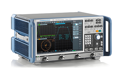
ベクトル ネットワーク アナライザ (VNA) – Sパラメータ測定用 (S11、S21)。
信号発生器とスペクトル アナライザー – VNA が利用できない場合の代替手段。
パワーメーター - 挿入損失の検証用。
パワーアンプとダミー負荷 – 高電力テスト用 (該当する場合)。
キャリブレーション キット (SOLT/TRL) – VNA キャリブレーション用。
ケーブルとアダプタ – 高品質で位相が安定した RF ケーブル。
温度チャンバー(必要な場合) - 熱安定性テスト用。
2. 準備
SOLT (ShortOpenLoadThru) キャリブレーションを使用して、VNA を目的の周波数範囲 (例: 1~10 GHz) までキャリブレーションします。
フィルターを適切に接続します (ケーブルの動きを最小限に抑えて適切な嵌合を確保します)。
フィルターのウォームアップ時間を確保します (特に高Qキャビティの場合、温度がパフォーマンスに影響します)。
3. 主要な測定
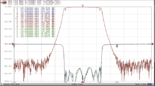
a) 周波数応答(S21 – 挿入損失と帯域幅)
周波数範囲全体で S21 (透過率) を測定します。
識別する:
中心周波数 (f₀) – 挿入損失が最も低くなる場所。
3 dB 帯域幅 – ピークからの損失が 3 dB 以下の周波数範囲。
挿入損失 (IL) – f₀ での最小損失 (可能な限り低く、たとえば 0.5 dB 未満である必要があります)。
シェイプ ファクター - 60 dB BW と 3 dB BW の比率 (スカートの急勾配を示します)。
b) リターンロス/VSWR(S11 – 入力整合)
S11 (反射) を測定してインピーダンス整合を確認します。
通過帯域におけるリターンロスは 15 dB 以上 (VSWR <1.5) である必要があります。
リターンロスが悪い場合は不一致(不適切な結合など)があることを示します。
ハ) 帯域外拒否
指定された周波数でのストップバンド減衰を測定します。
スプリアス応答(予期しない通過帯域)がないか確認します。
除去が仕様を満たしていることを確認します (例: f₀ から ±500 MHz で >60 dB)。
d) 群遅延(位相直線性)
VNA のグループ遅延測定 (位相の微分) を使用します。
信号の歪みを最小限に抑えるには、通過帯域内でフラットである必要があります。
e) 電力処理(該当する場合)
f₀付近で高出力信号(CW またはパルス)を適用します。
劣化(アークまたは加熱を示す)の前後で S21 を監視します。
温度上昇を測定します(高出力フィルターの場合)。
f) 熱安定性(重要な用途向け)
フィルターを温度チャンバー内に置きます。
温度(例:40°C ~ +85°C)による周波数ドリフトと IL 変動を測定します。
4. 仕様に対する検証
結果をデータシートまたは設計目標と比較します。
通過帯域リップル (最小限である必要があります、たとえば、0.2 dB 未満)。
帯域幅 (必要な 3 dB または 1 dB BW を満たす必要があります)。
除去(阻止帯域で必要な減衰を満たす必要があります)。
電力処理能力(定格電力で劣化なし)。
5. よくある問題のトラブルシューティング
挿入損失が高いですか? → 結合不良や導体損失がないか確認してください。
リターンロスが悪いですか? → 適切なインピーダンス整合を確認します (調整ネジの調整が必要な場合があります)。
非対称な対応? → 製造上の欠陥の可能性があります(共振器の位置ずれ)。
周波数ドリフト? → 熱膨張の影響(材料特性)を確認します。
6. 上級テスト(オプション)
相互変調歪み(IMD) → 高出力フィルター用。
位相ノイズ寄与 → 発振器ループで使用する場合。
振動/衝撃試験 → 軍事/航空宇宙用途向け。
結論
Sパラメータ、電力処理能力、熱安定性を体系的に測定することで、キャビティバンドパスフィルタの性能を完全に検証できます。結果を必ず文書化し、設計仕様と比較することで、コンプライアンスを確保してください。
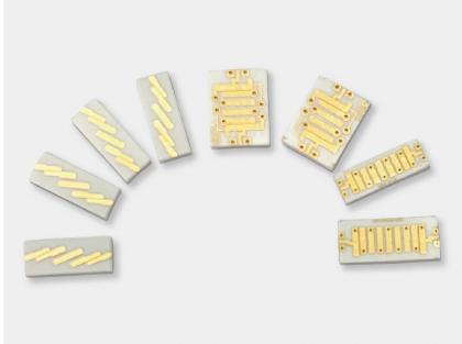
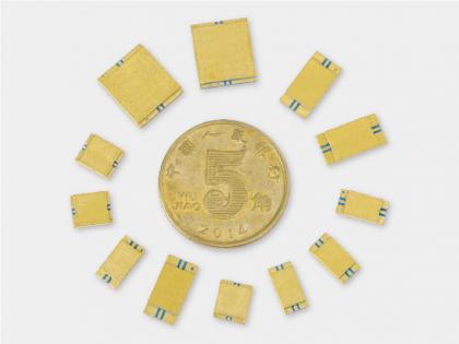
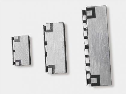
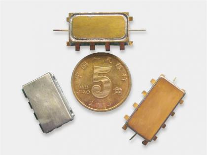
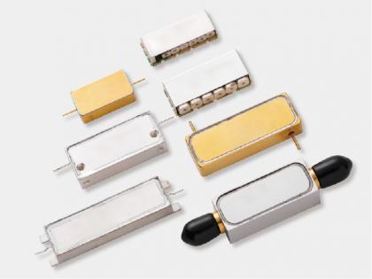
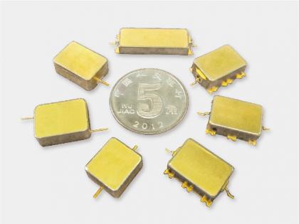
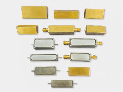
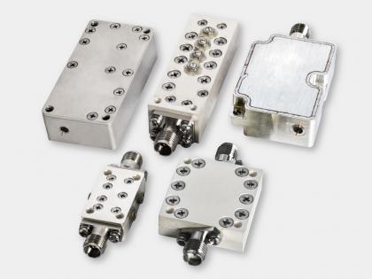
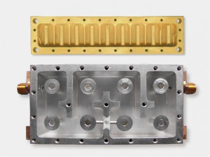
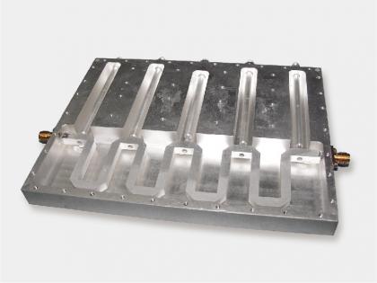
Yun Micro は、RF パッシブ コンポーネントの専門メーカーとして、バンド パス フィルター、ロー パス フィルター、ハイ パス フィルター、バンド ストップ フィルターを含む最大 40GHz のキャビティ フィルターを提供できます。
お問い合わせをお待ちしております: liyong@blmicrowave.com

住所 : Xisan Road, Mechanical and Electrical Industrial Park, No.767 Yulan Road, Hefei,Anhui.
tel : +86-18855146875
Eメール : liyong@blmicrowave.com


それをスキャンします